Complete Guide to an Easy DIY Wireless Charger Build
📗👇
Looking for an opportunity to build a useful tech gadget, a little outside of your comfort zone?
This DIY wireless charger project is the perfect opportunity to merge your techy and creative hobbies. Anyone can build this DIY wireless charger in under an hour with NO prior electronics know-how required.
KeyBuildingBlocks is supported by its audience and customers. When you purchase through links on our site, we may earn a small affiliate commission.
DIY Wireless Charger Build Guide
| ✔️ Difficulty Level: Easy | ✔️ Material Cost: <$30 | Result: 10W slim wireless charger with cool light |
| ✔️ Skillset Required: Functioning adult. *Can use Amazon and a glue gun 🙂 | ✔️Time: <1 hour |
Required Supplies for the DIY Wireless Charger
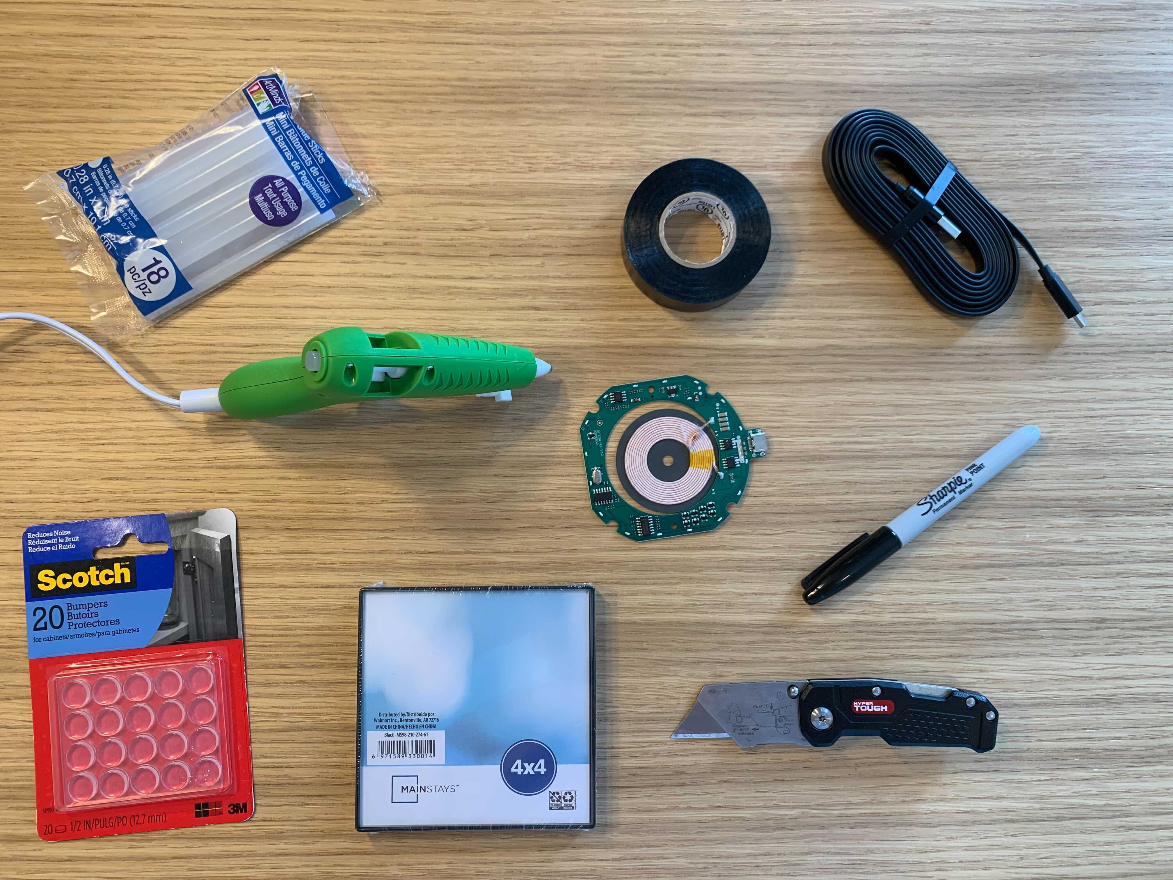
Materials
- 7.5W/10W wireless charger PCBA (Printer Circuit Board Assembly)
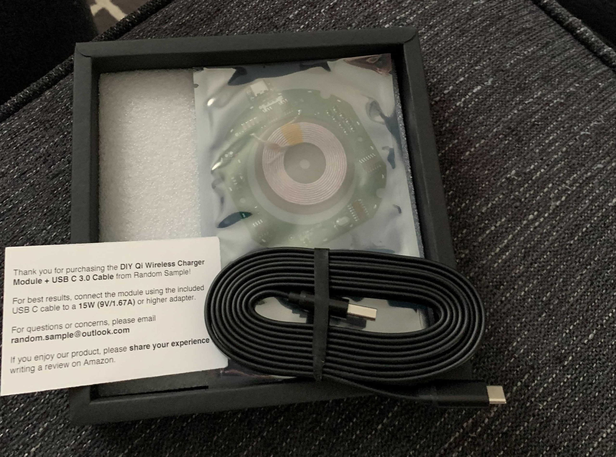
- This kit on Amazon comes with everything you need to charge wirelessly, without soldering
- (1) Wireless charger PCBA with 16 indicator lights
- Compact design
- (1) 6 foot USB-C cable
- This kit on Amazon comes with everything you need to charge wirelessly, without soldering
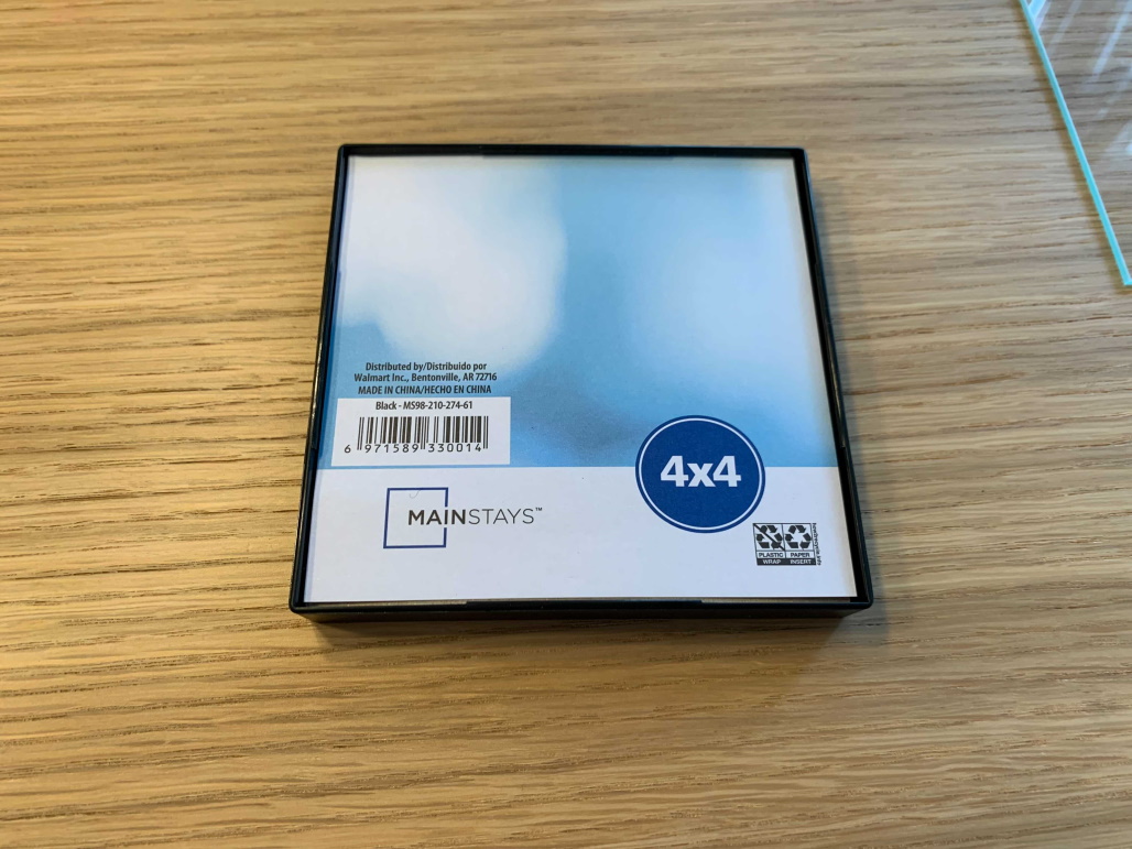
- 4″ x 4″ picture frame with plastic edges
- Available at Walmart or your local craft store
- 1/2″ bumper protectors
- Use 4 bumpers to secure the glass top
- (optional) Use 4 as feet for the charger once assembled
- (optional) Electric tape
- (optional) Wall charging adapter
- For best results use a 15W+ wall adapter(9V/2A)
- Alternatively, you can use a laptop or any other USB output port to power the wireless charger
Tools 🧰
- Hot glue gun with glue sticks
- Foldable utility knife like this one on Amazon
- Sharpie marker
- (optional, but helpful) Needle nose pliers
Instruction to Make the DIY Wireless Charger
Part 1 – Getting Started
- Ensure you have all required materials and tools to build the DIY wireless charger
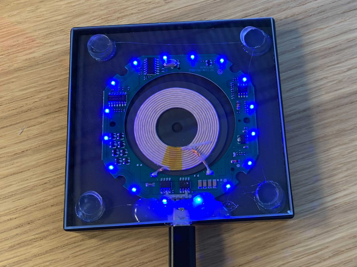
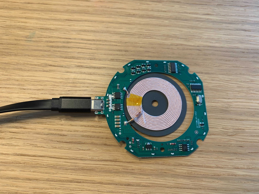
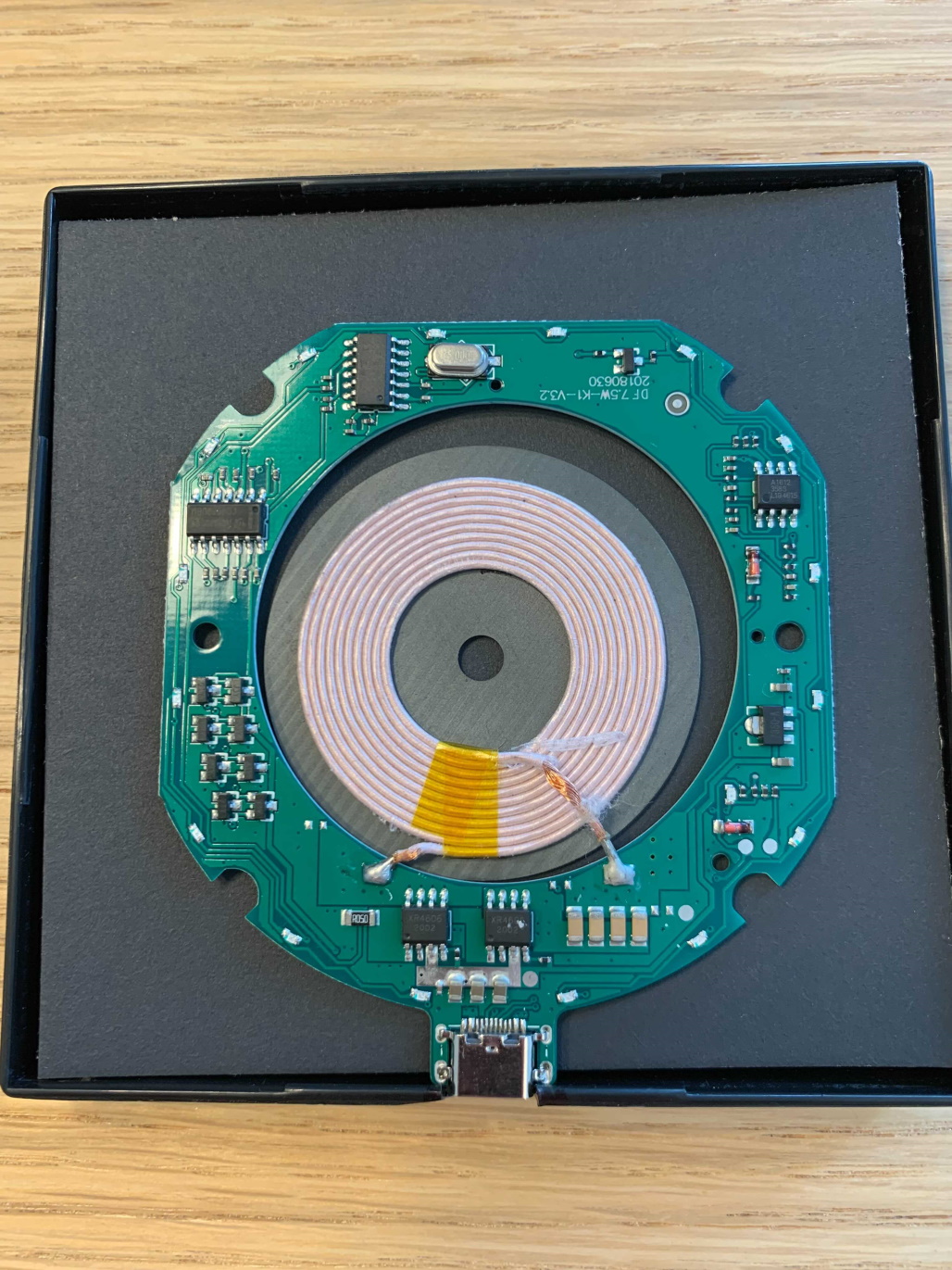
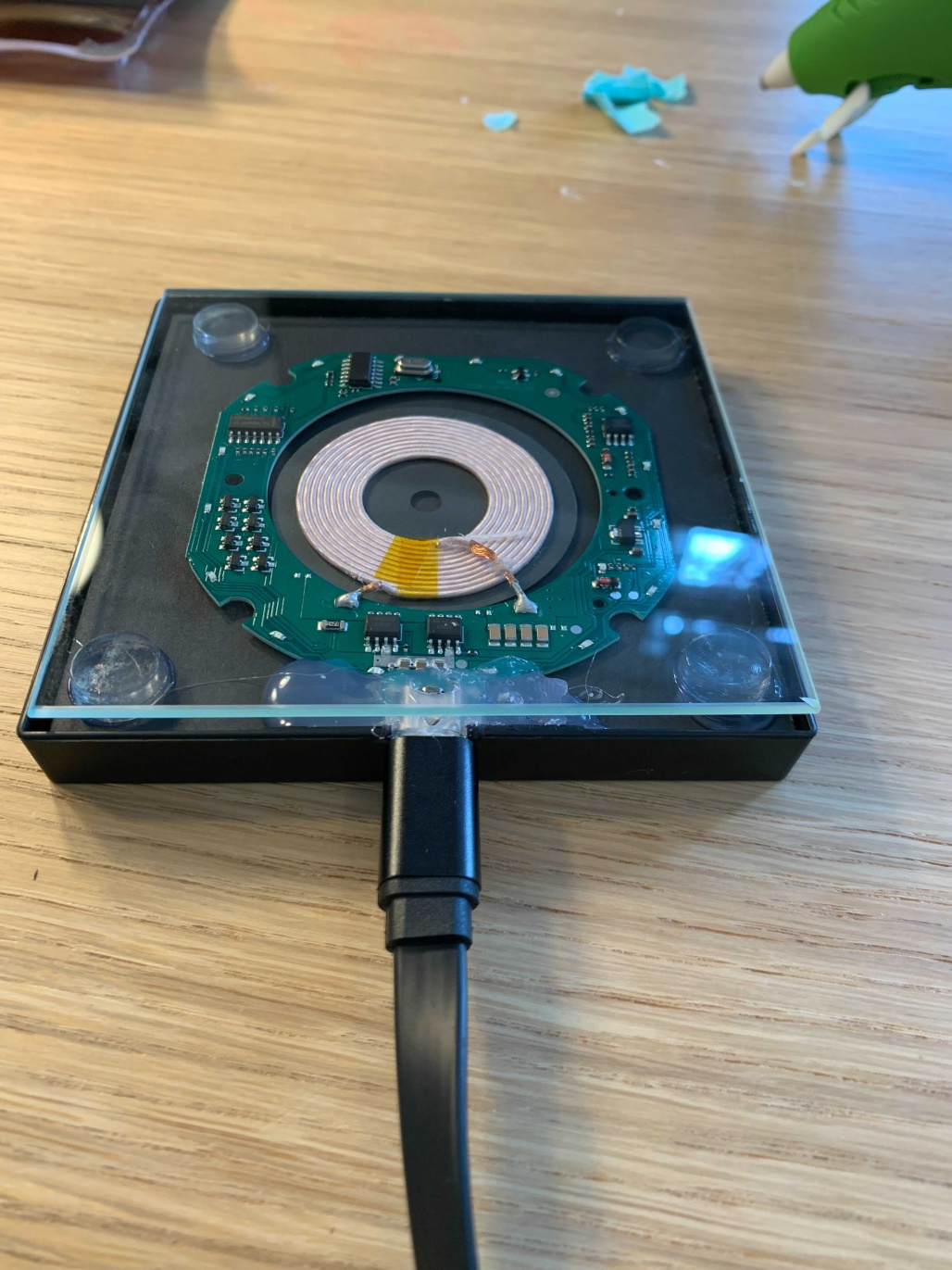
- Test the wireless charger PCBA as soon as received from Amazon
- Open the wireless charger PCBA and unwrap the USB-C cable
- Carefully attach the USB-C cable to the PCBA
- Set the wireless charger PCBA down on a flat surface
- Plug the USB end of the cable into your computer or wall adapter
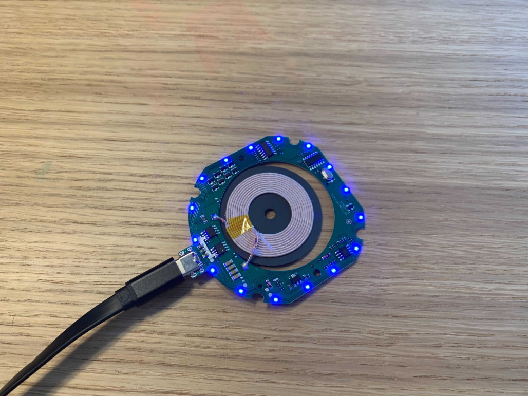
- ENSURE it lights up, else exchange with vendor

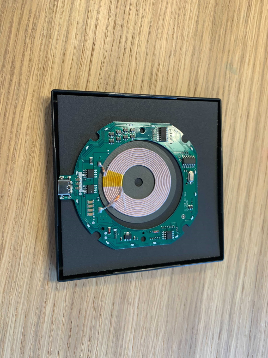
Wireless charger PCBA works and lights up Lights turn off when not active Contents of the wireless charger PCBA from Amazon
- Plug in glue gun so it is heated up when needed
- Remove the USB cable from the wireless charger PCBA
- Won’t need this again until the end
- Prepare the picture frame for later PCBA installation
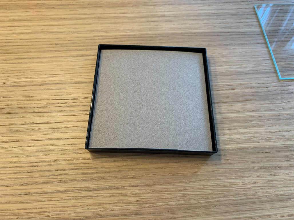
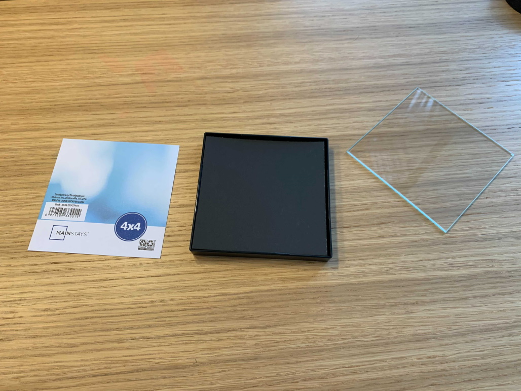
- Open and unwrap the picture frame
- Remove glass panel and set to the side
- Remove picture insert
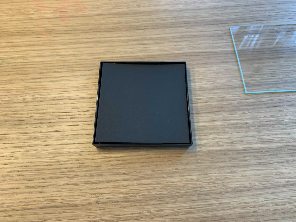
- Flip cardboard over so the black side is facing up (towards the glass)
- Keep glass removed
Before Step 5.4 After Step 5.4 Final result of Step (5) with the black background for the DIY wireless charger
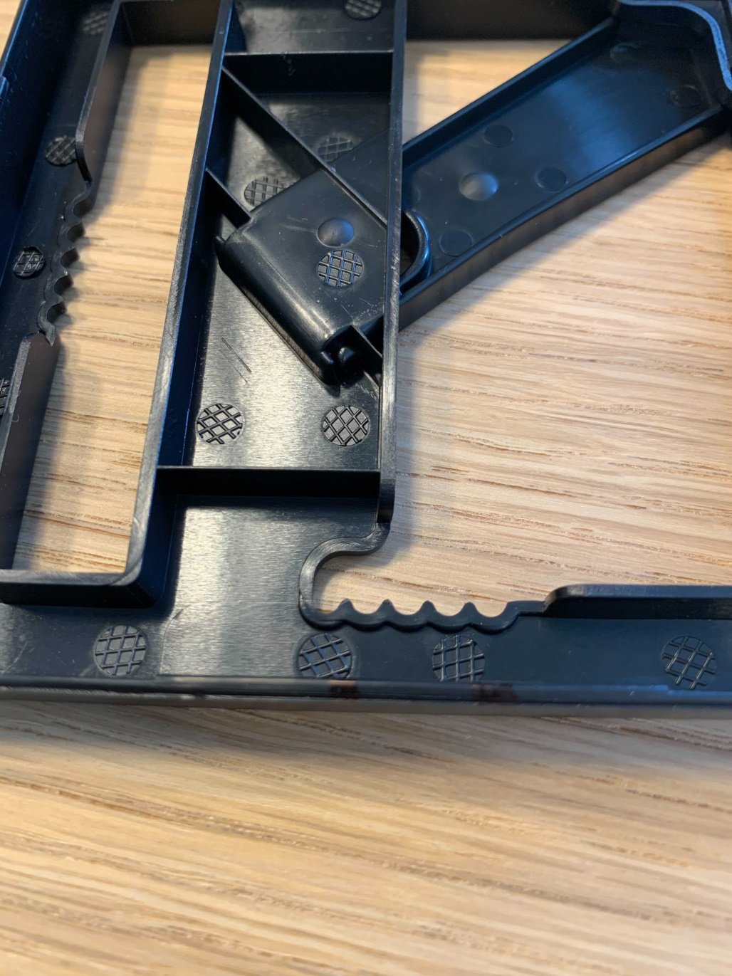
Part 2 – Make Hole for the Charger’s USB-C Port
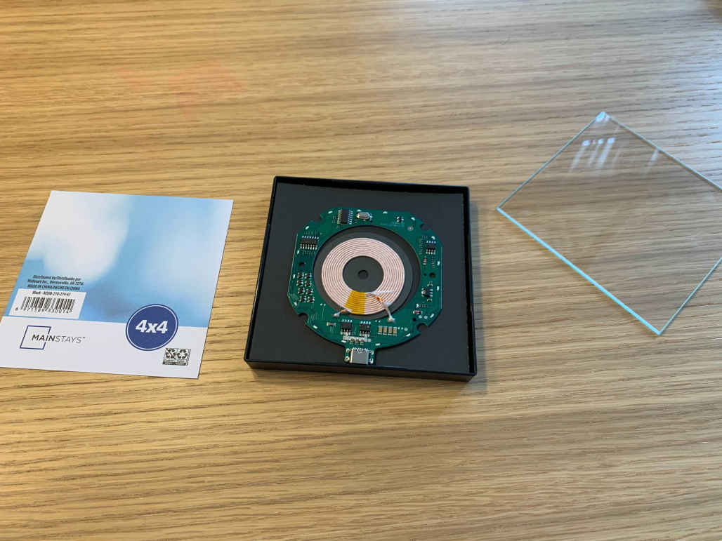
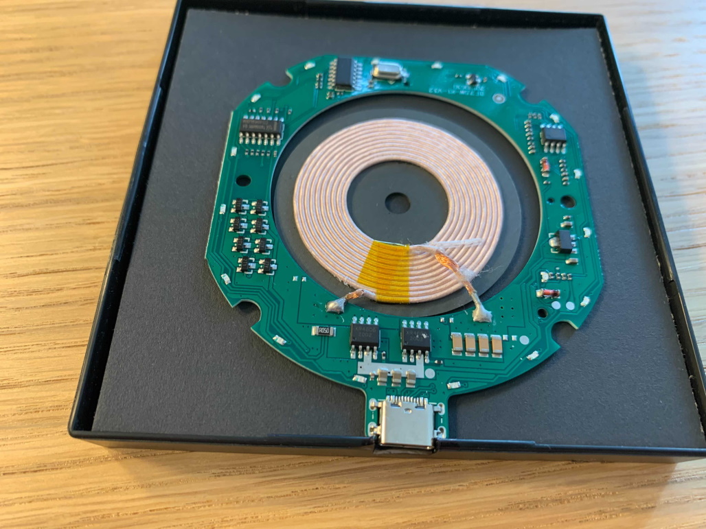
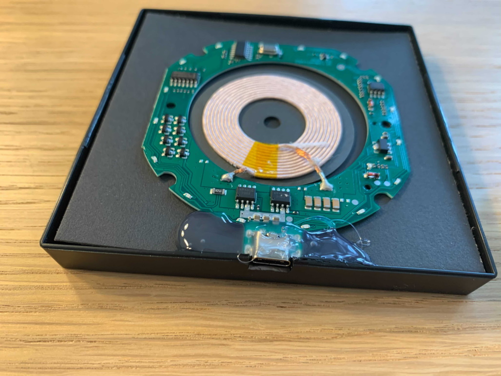
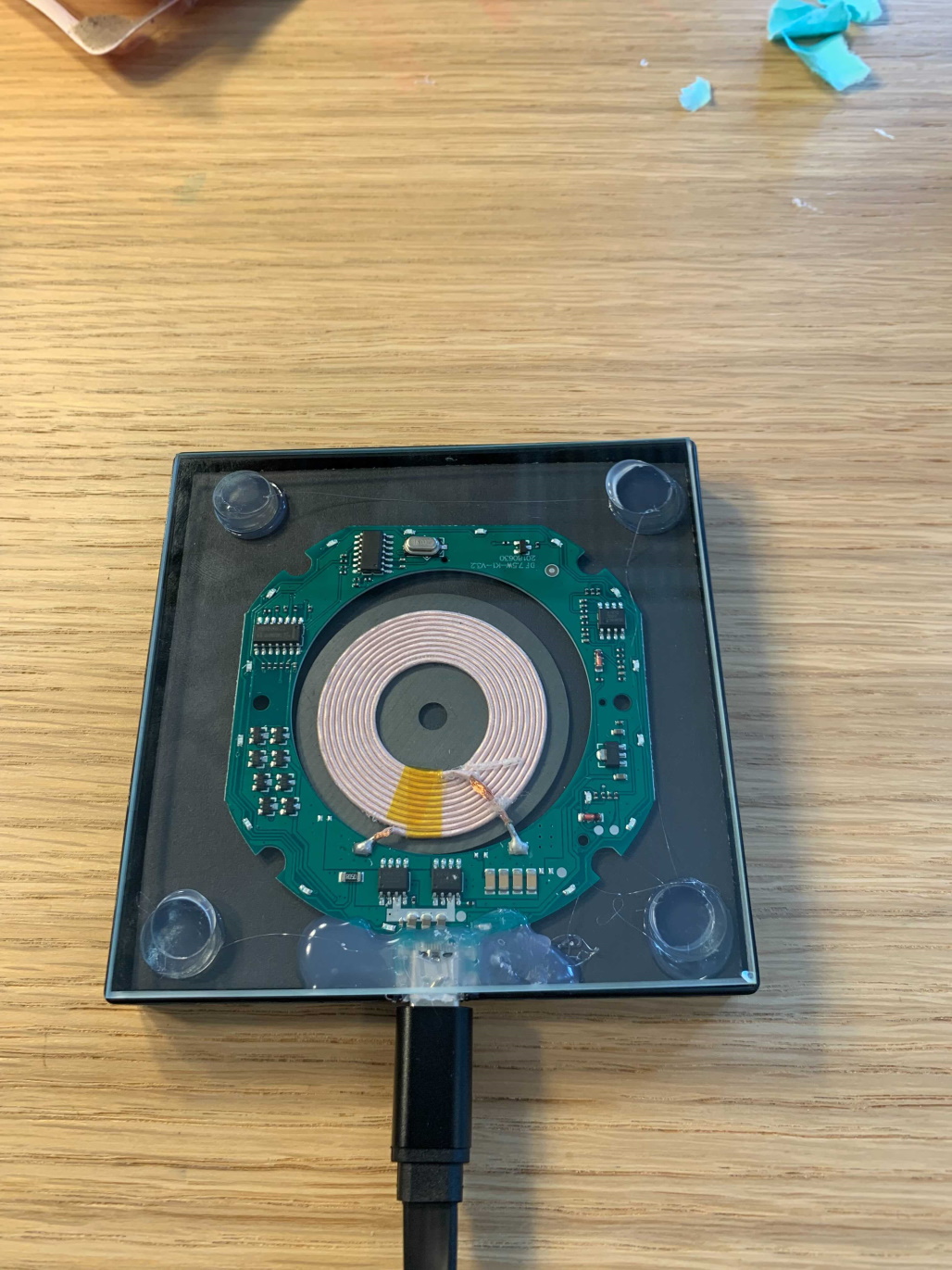
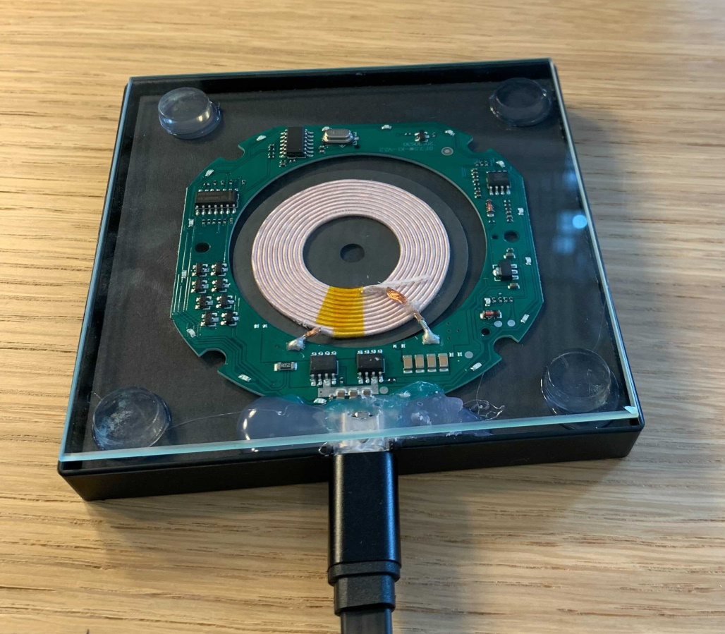
- Place the bare wireless charger PCBA into the picture frame, on top of the black cardboard
- Ensure circuit board fits; there should be plenty of space
- Place the USB-C end of the PCBA near a wall of the picture frame
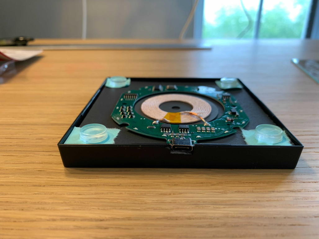
- Carefully set the glass on top of PCBA, to ensure it looks as you like, visually
- NOTE: The glass will not fit in the frame all the way. This is expected. We address it later
- Remove the glass frame
- Set it to the side for later
USB-C end placed near wall of picture frame Sharpie marks on right and left of USB-C slot to cut
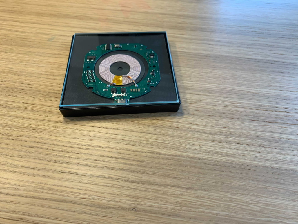
- With the PCBA aligned in the frame as you like, use a Sharpie marker or pen to mark the left and right sides of the USB-C end onto the picture frame
- We need the USB-C to be exposed outside of the frame
- Sorry the black Sharpie is a little hard to see in the pics
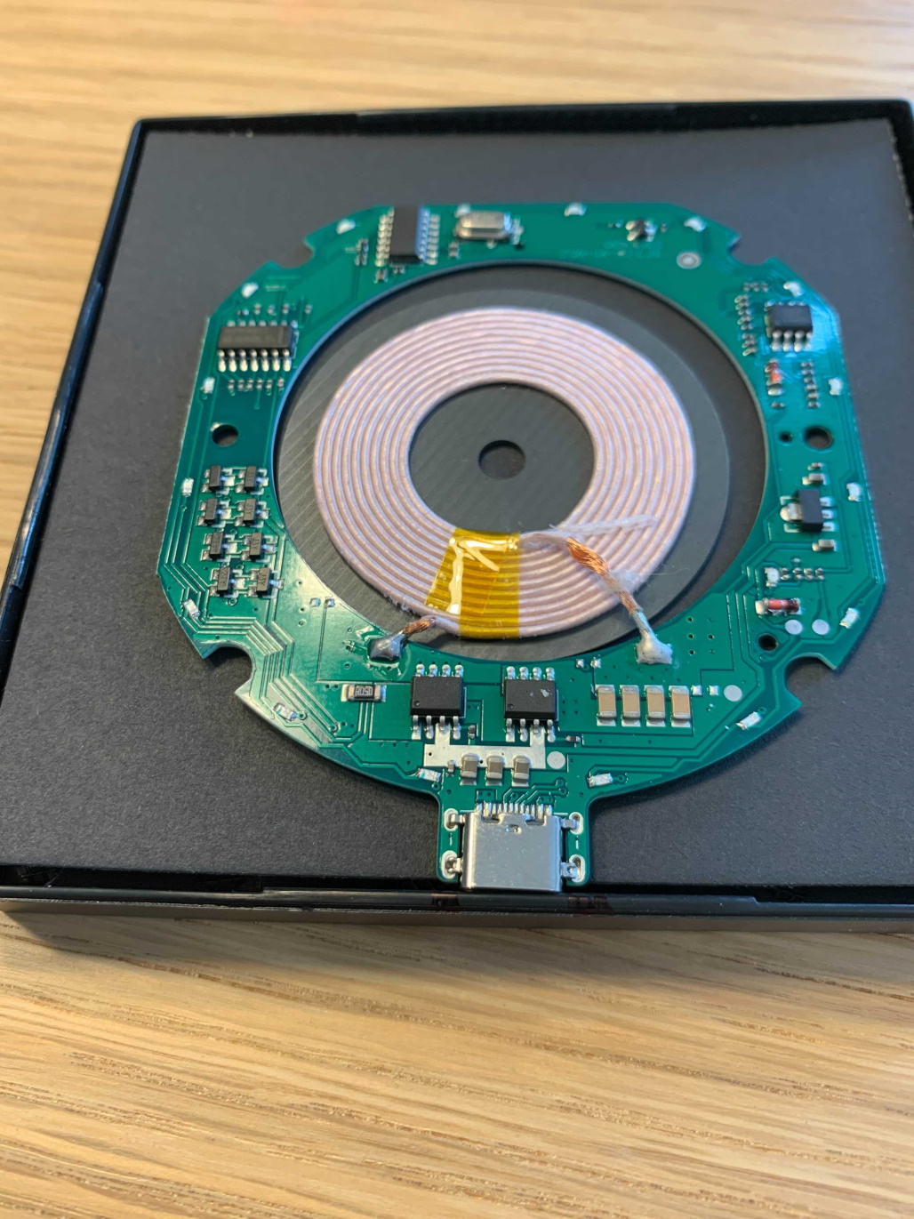
- NOTE: We want the metal of the USB adapter on the chip to be exposed but the green laminate should stay inside the frame.
Sharpie marking USB-C slot to cut USB-C slot marked in sharpie
- Remove the wireless PCBA AND black cardboard background from the frame
- Set to the side while we work on the frame
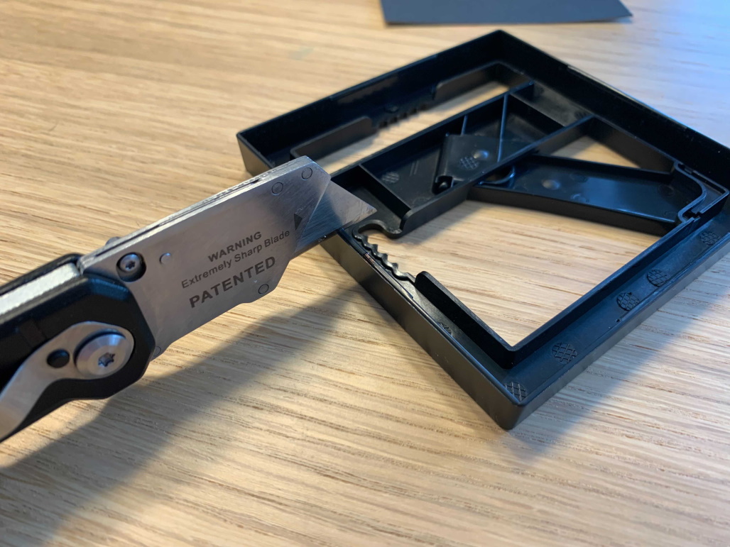
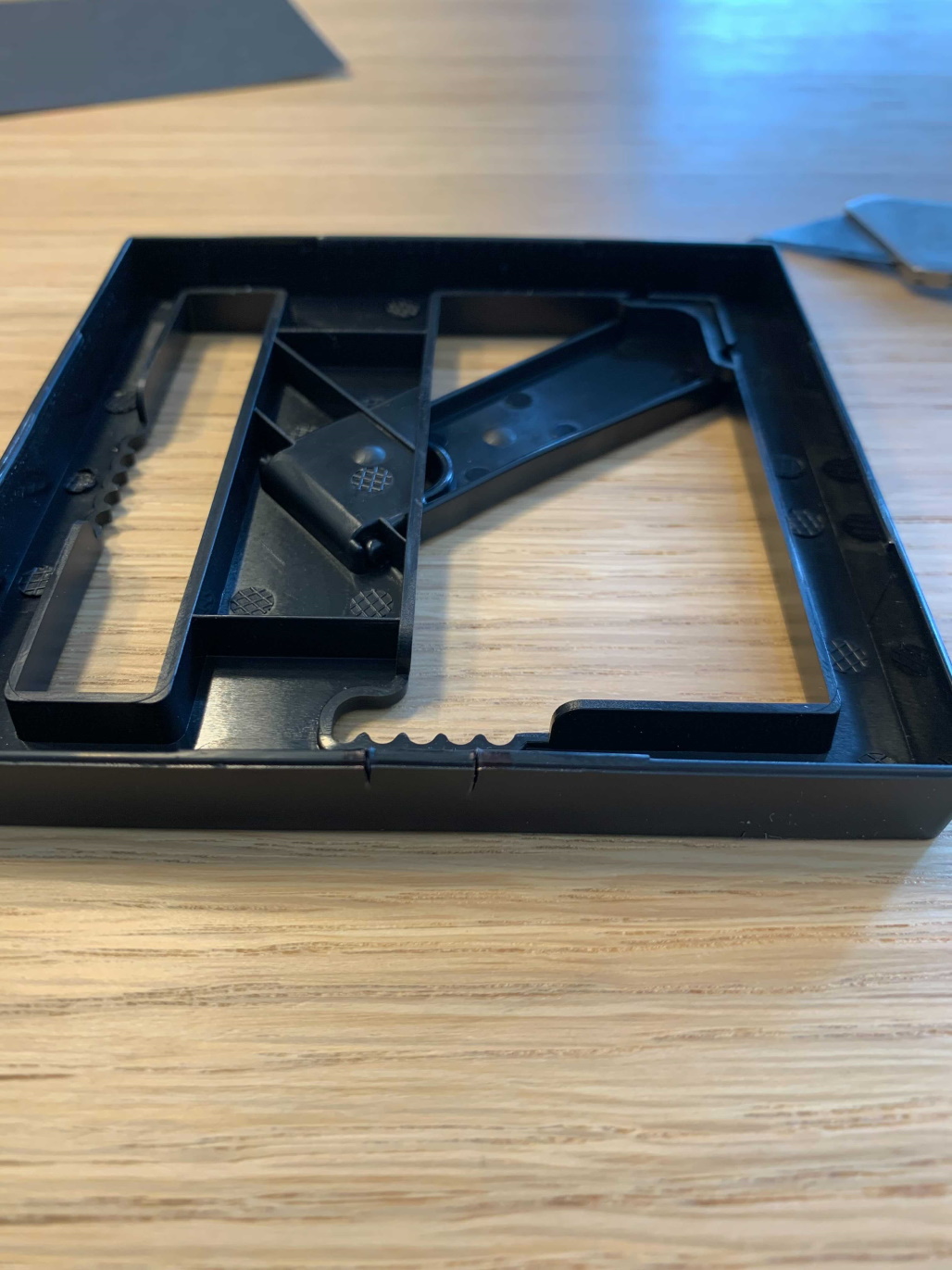
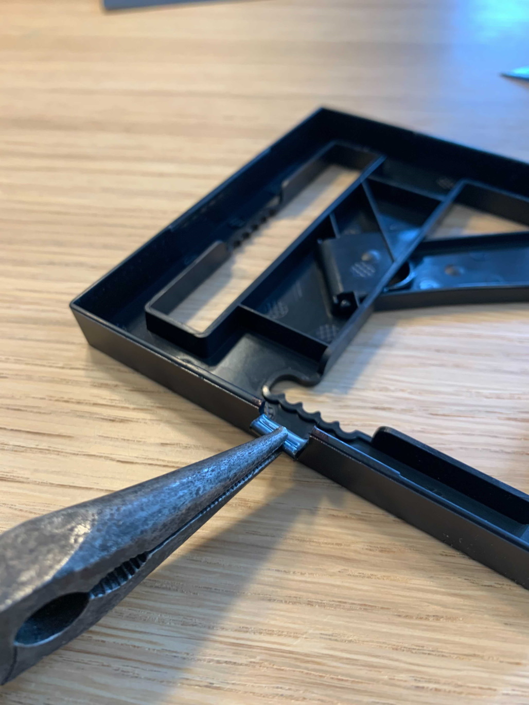
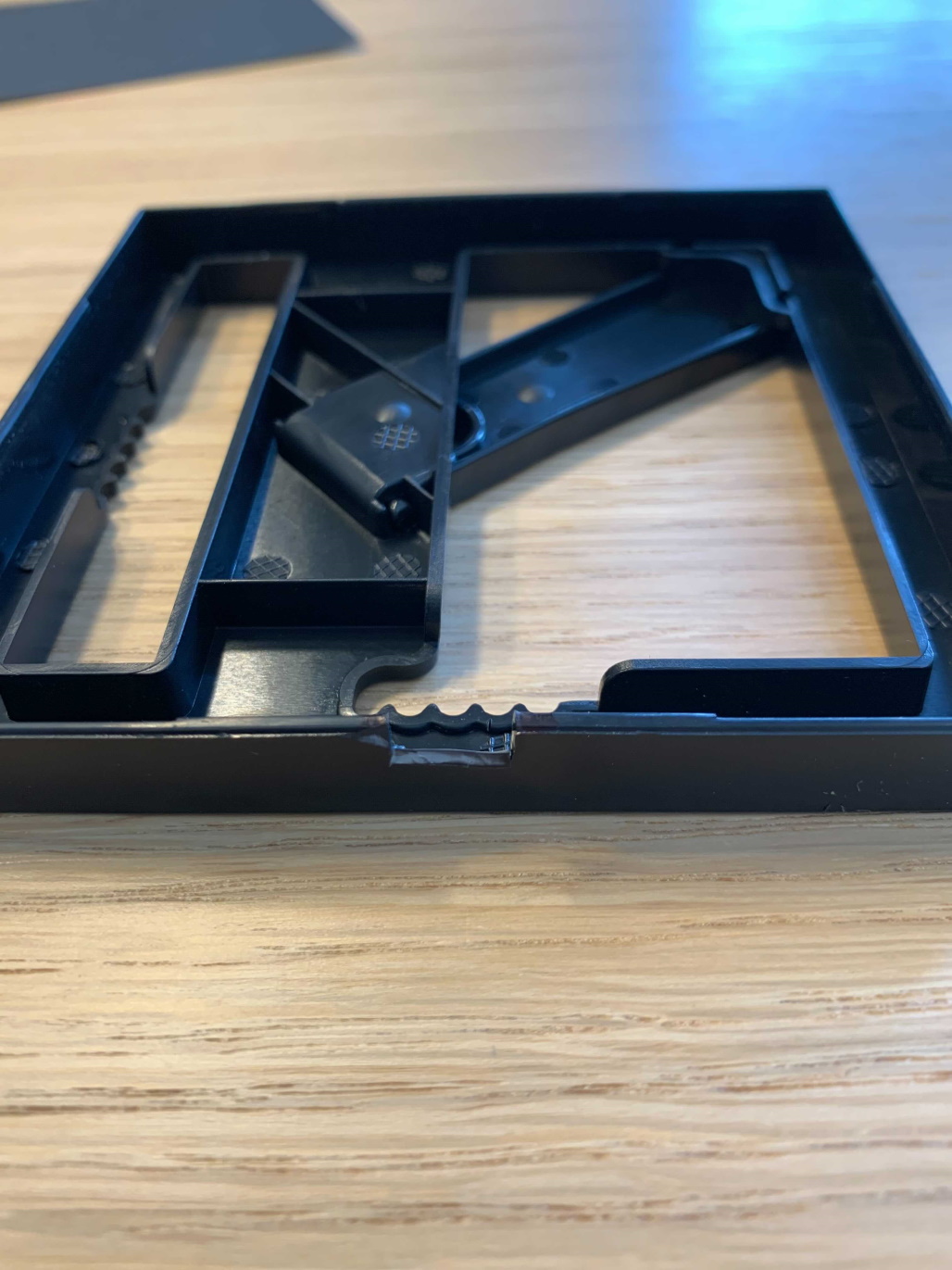
- Using your utility or exacto knife, carefully, cut a small gap in the side of the picture frame for USB cord to plugin
- Cut to the depth of the USB-C port
- Remember it is better to cut too small at first and widen later so the adapter will fit
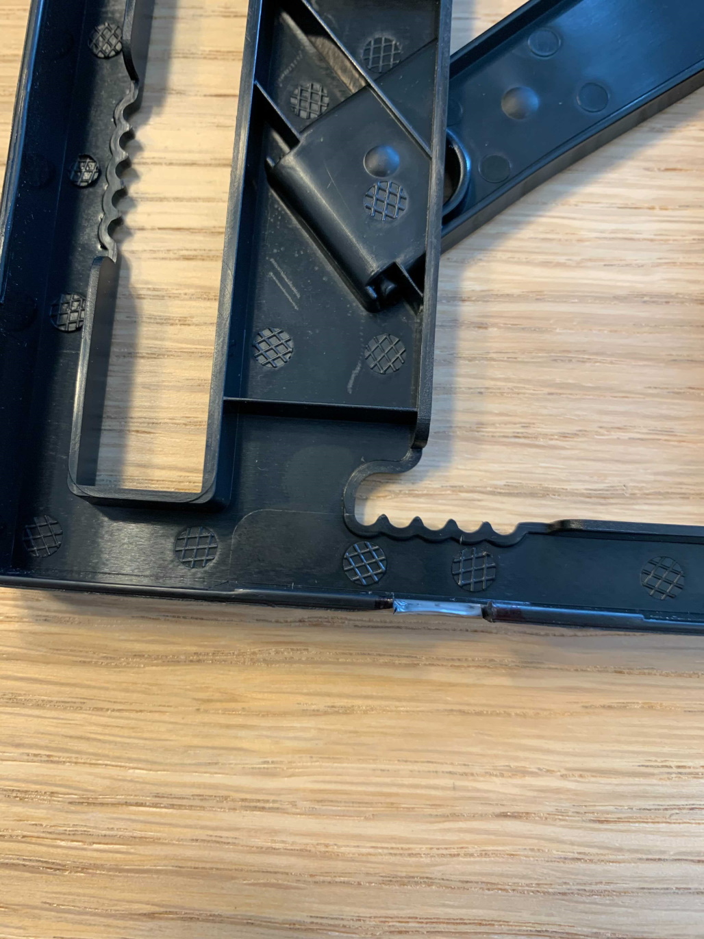
- TIP: Use a pair of needle nose pliers to help peal the thin tab/lip back from the frame to easily cut the bottom
Cut each side Both sides cut to depth Use needle nose pliers to flex plastic tab Plastic lip/tab is removed
- Put cardboard back (black side up) and wireless PCBA back in the picture frame with the USB port lined up
- Make any adjustments to the USB port cutout BEFORE moving forward
Part 3 – Secure the DIY Wireless Charger
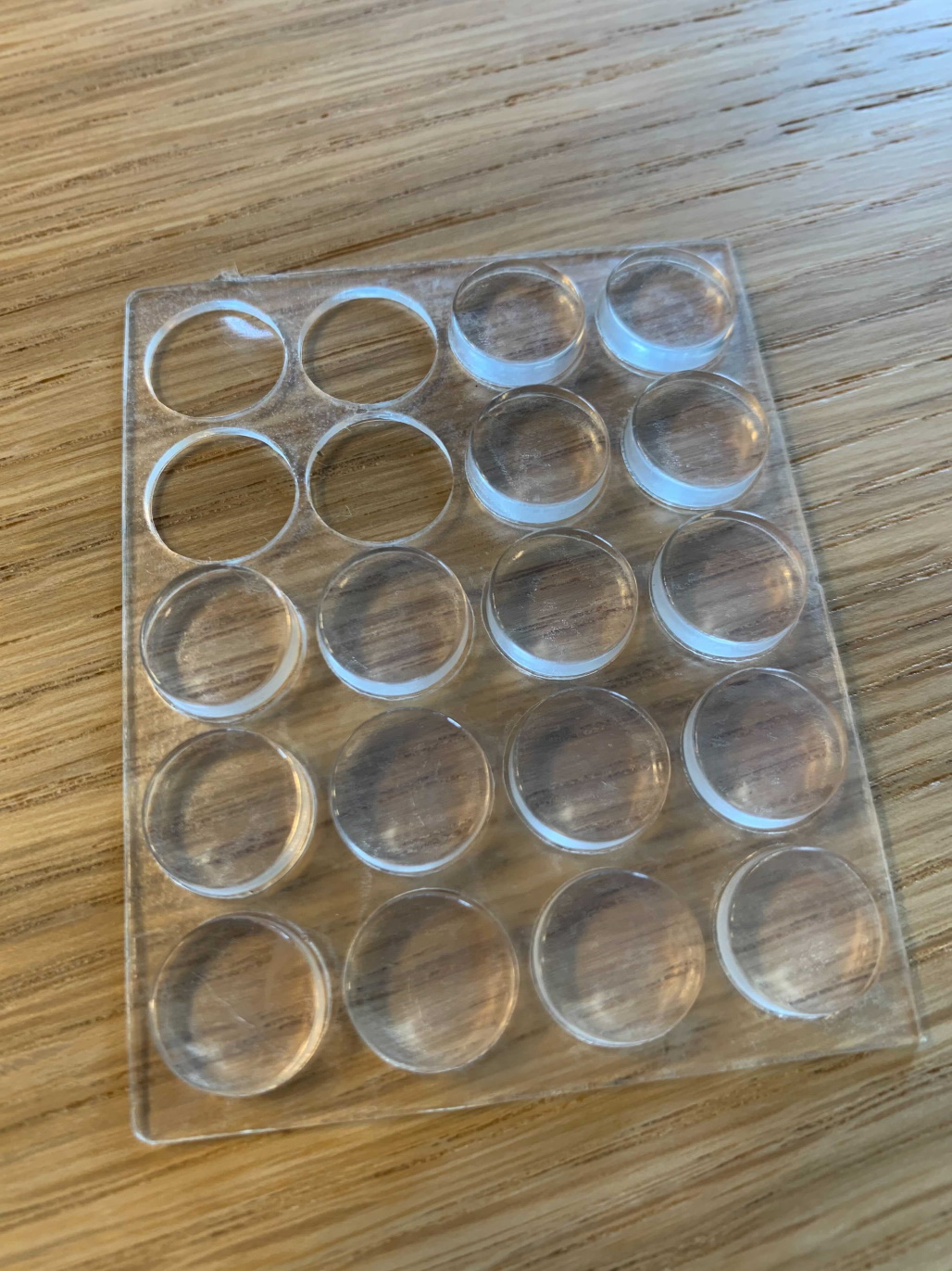
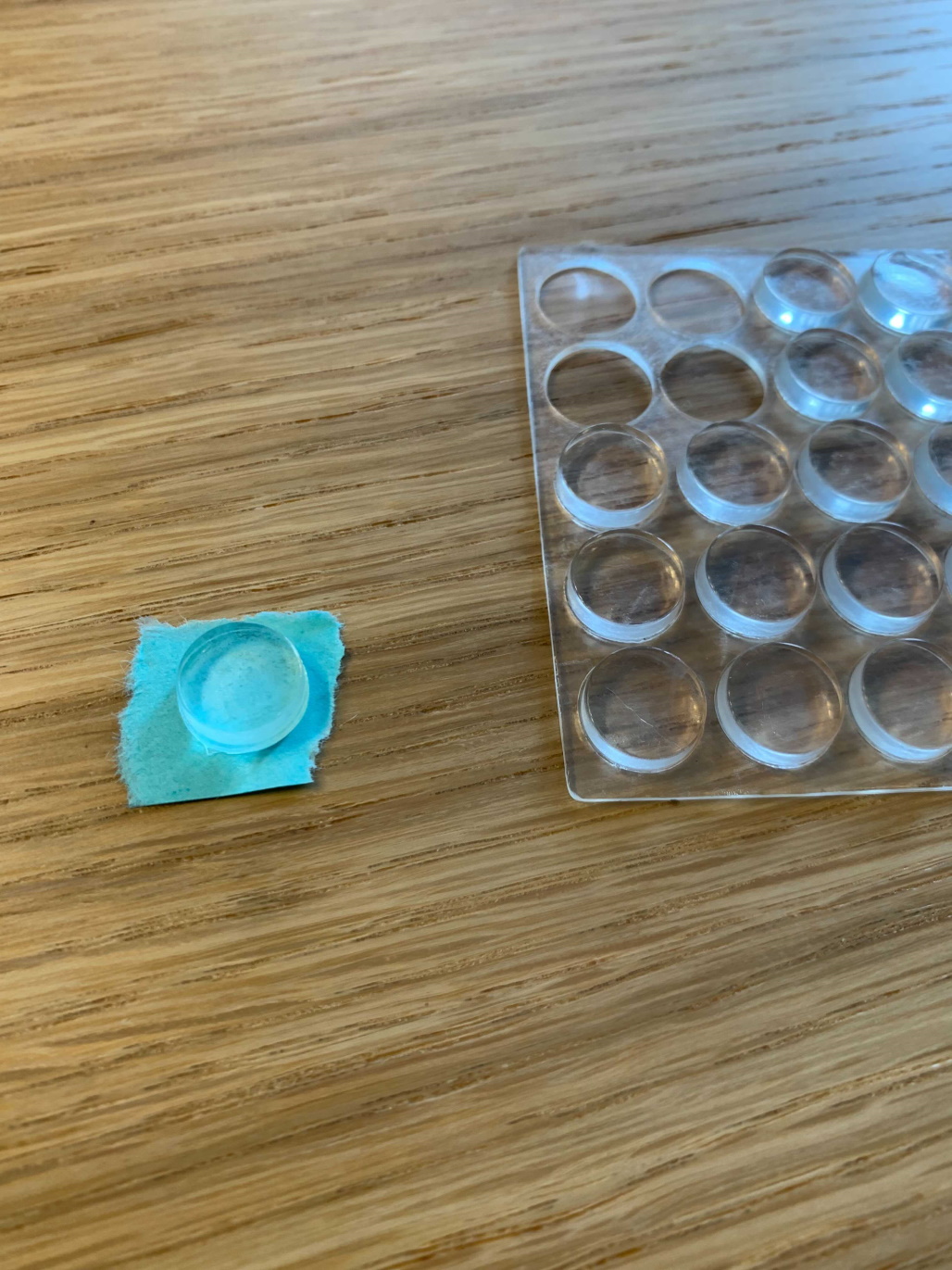
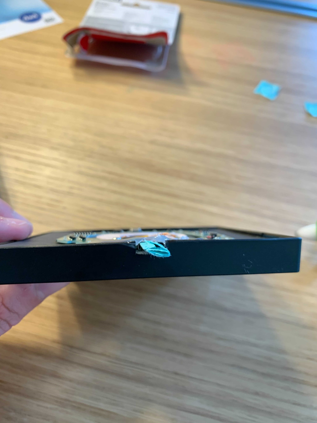
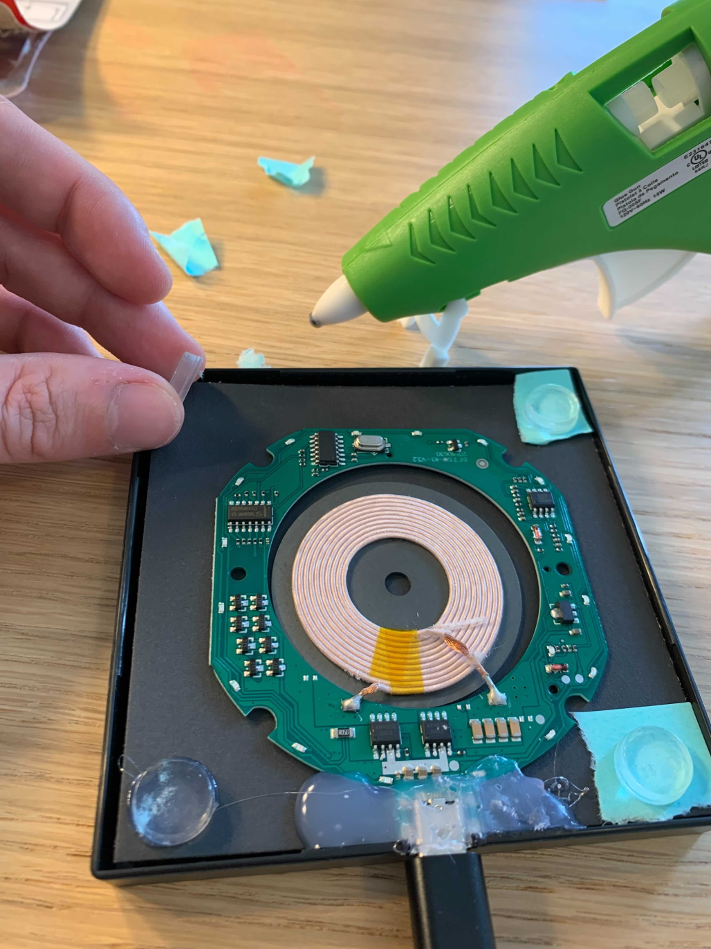
- Place 1/2” bumpers at the 4 corners of the picture frame on the black cardboard background
- My bumpers have 1 sticky side, so I used small pieces of blue paper to STOP THEM FROM STICKING because we need to test placement before adhering to their final postion
- Placing the bumpers in the 4 corners will line up perfectly with the picture frame’s supports
Remove 4 bumpers from pack Place sticky side of bumper on blue paper Place 1 bumper in each corner of picture frame Bumpers placed on top of picture frame supports
- WITHOUT SECURING the 1/2” bumpers, place the glass on top of the frame and spacers
- Ensure the glass is no longer pressing on the wireless PCBA components. That is, the bumpers fully support the weight of the glass frame
- Ensure the bumpers are stable when pressing the glass down
- You may want to take a picture or mark points of reference for later when securing
- Remove the glass and set to the side
- Remove the 1/2” bumpers from the frame, so we can work with the PCBA and frame
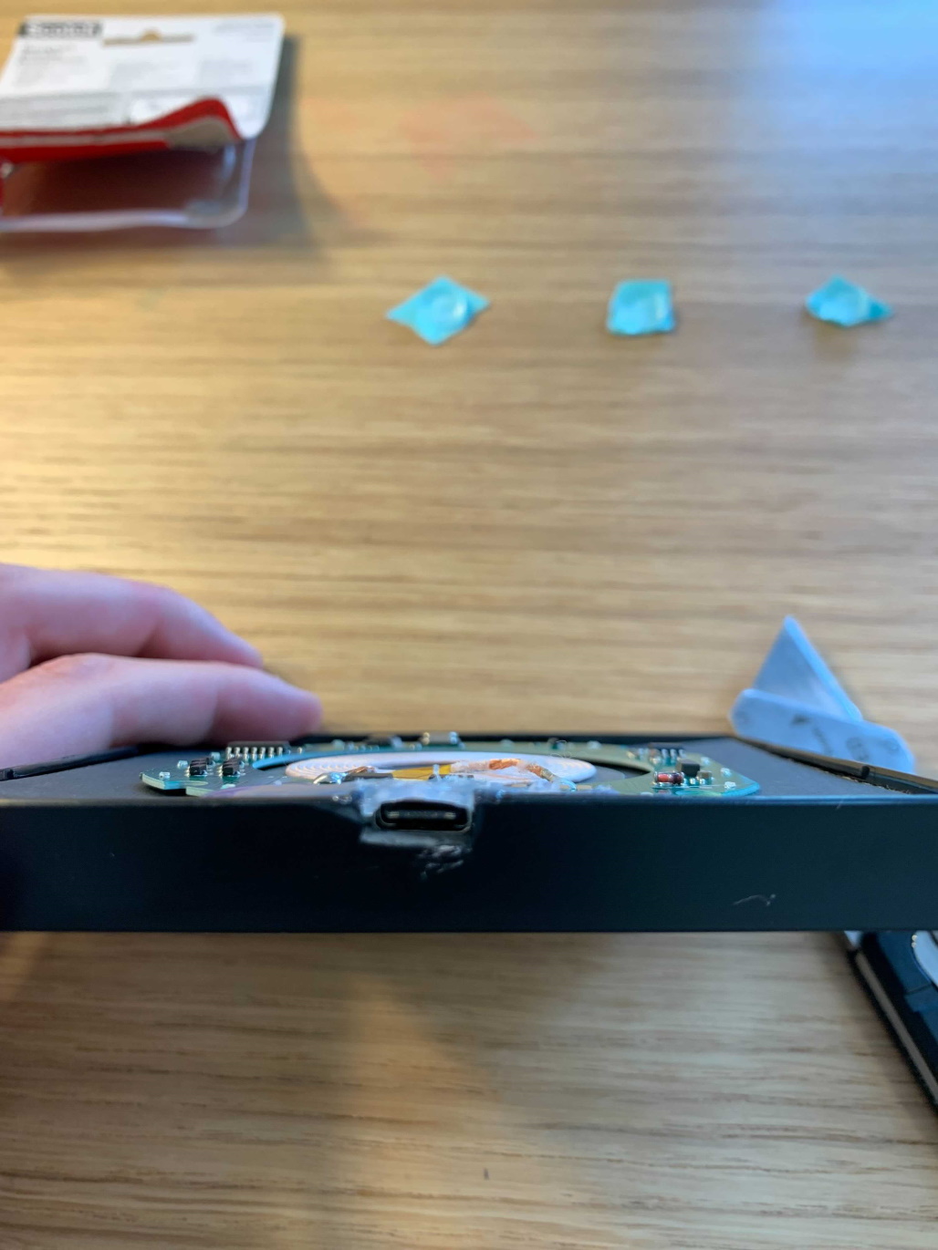
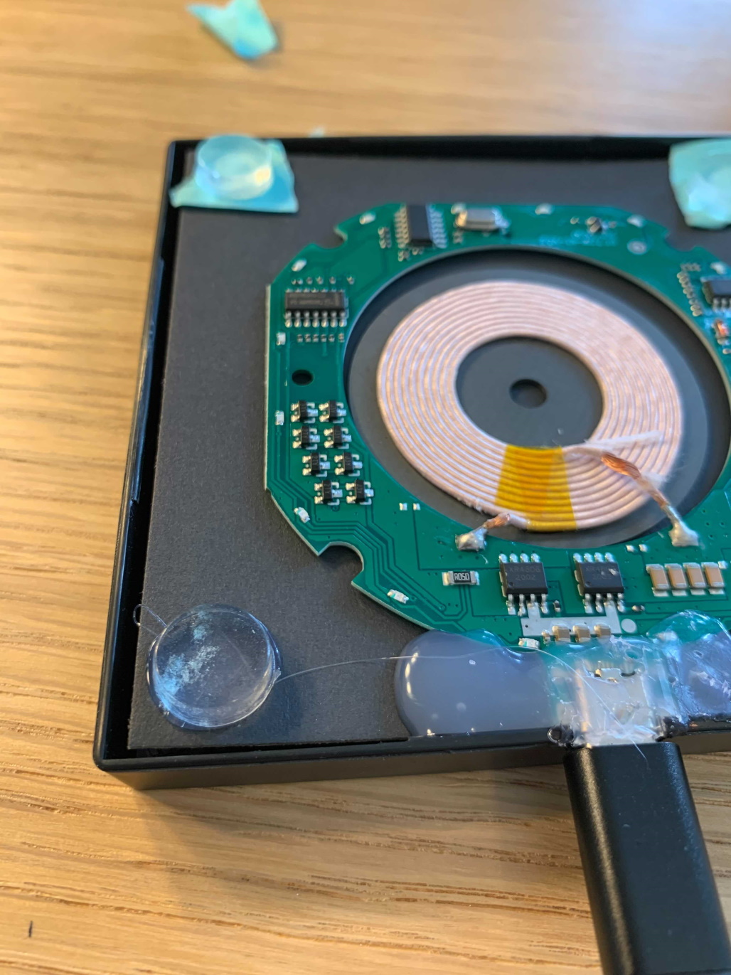
- Use a lot of hot glue to secure the USB end of the chip to the cutout in the frame
- Lineup the metal USB end with the hole we cut in the frame earlier
- Remember, the green chip should remain inside of the frame with only the metal port emerging through the cutout
- DO NOT GET glue in the USB-C slot (it will be a pain to get out)
- TIP: Fill the port with small, wrapped rolls of loose paper to avoid the hole getting glue in it
- Apply hot glue. Be liberal with the glue
- May consider securing the chip on the backside with glue so it is equally supported from pressure
- Must support the pressure of plugging and unplugging the USB-C end into the the power cable
- Lineup the metal USB end with the hole we cut in the frame earlier
- Wait for the glue to dry
- Remove paper from the USB port
- Carefully scrape away any glue that may have got on the cardboard or frame
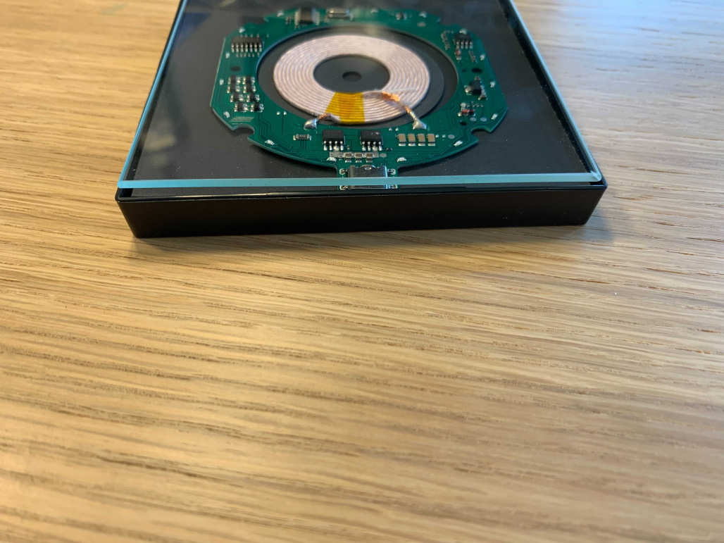
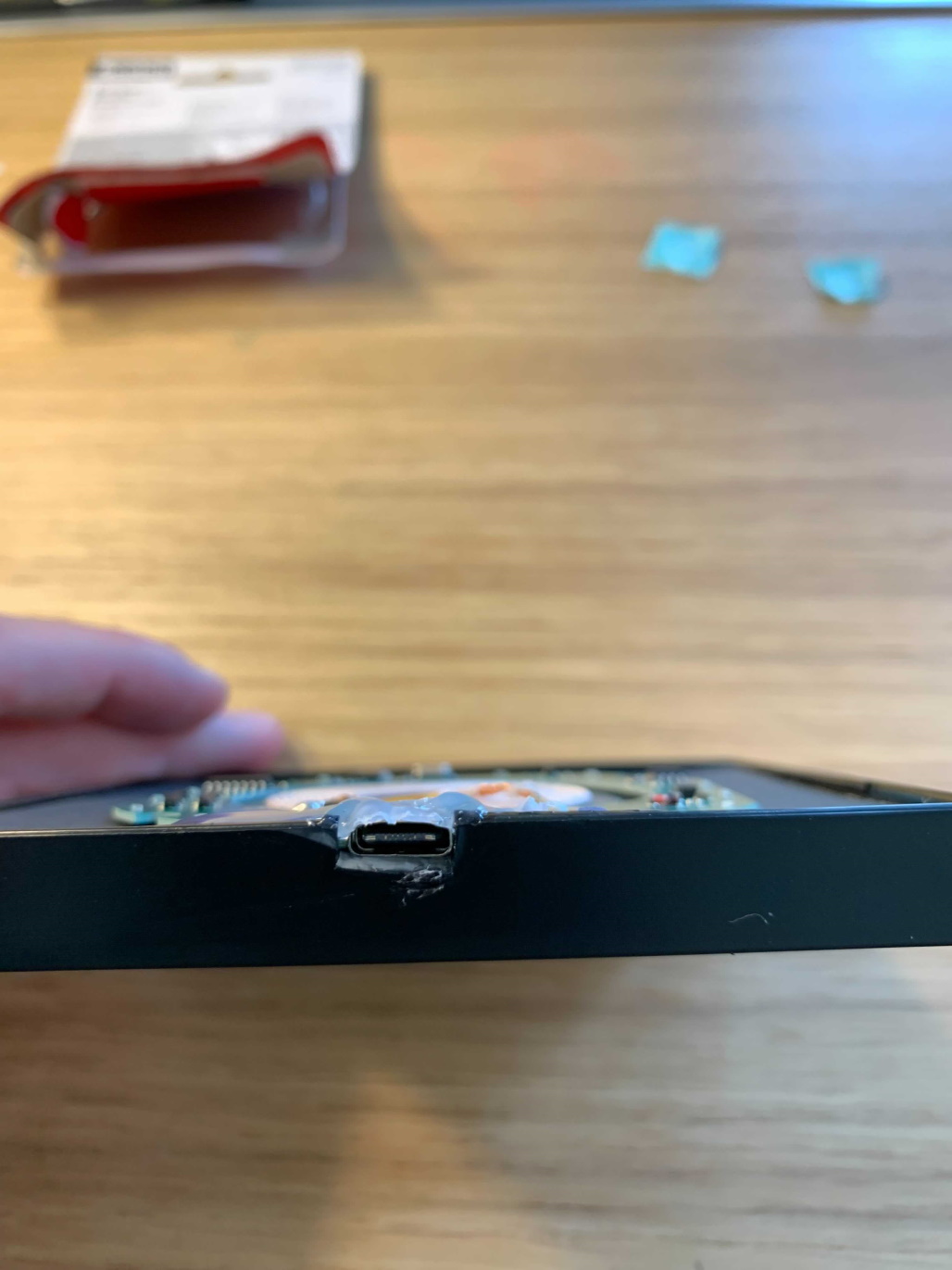
- Scrape away excess glue from the top of the USB port, so it is flat and the glue is not taller than the frame side.
- When the glass is placed it must be aligned with the top of the frame
- USB port should be visible
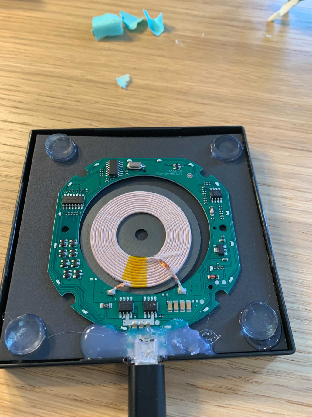
The PCBA chip is secured to the frame with hot glue The hot glue securing the USB-C port is not taller than the side of the frame USB-C port is secured to the frame with a liberal amount of hot glue Rolled paper is placed in the USB-C port to prevent glue from clogging the hole

Part 4 – Finale – Add the Glass Top to the Wireless Charger
- Plugin the USB-C cable to the port of the glued wireless charger PCBA
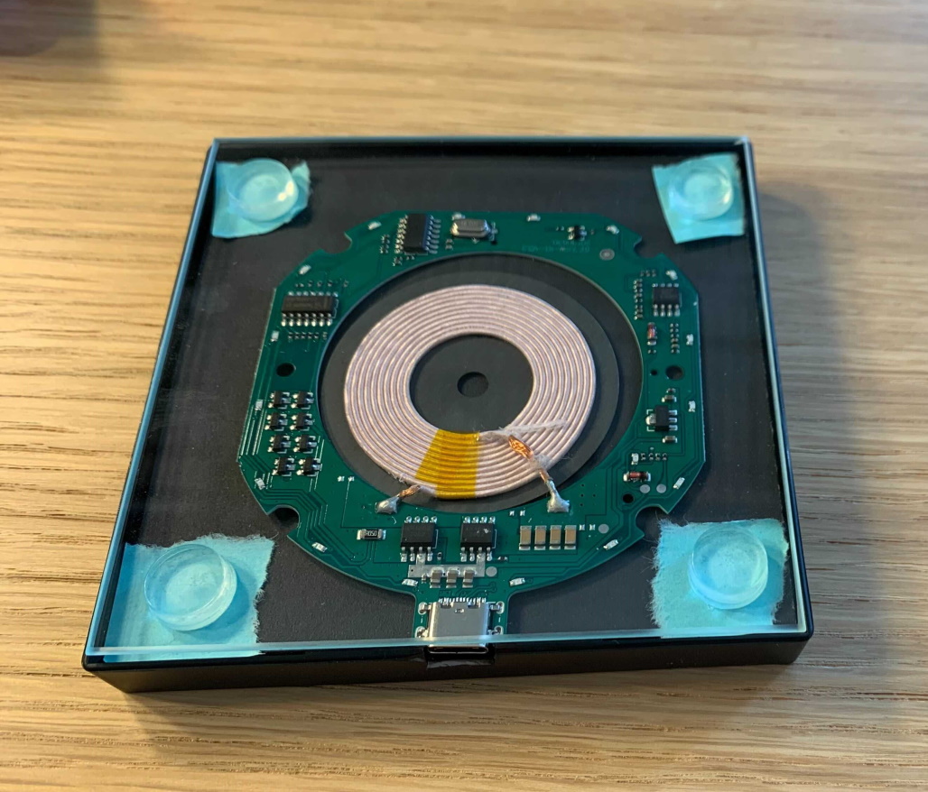
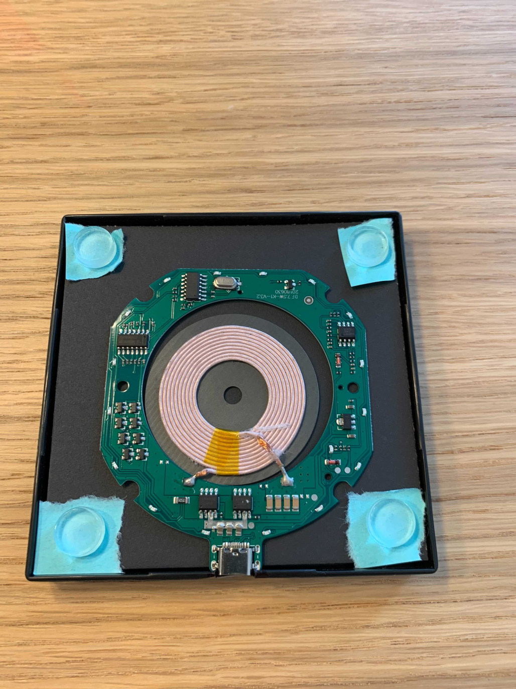
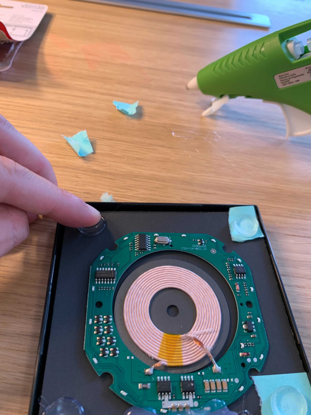
- Place the 1/2” bumpers in the location we planned earlier. Then using a small amount of hot glue, secure the 1/2” bumpers to the black cardboard where you previously marked
- Apply small amount of glue to one side of each bumper, one-at-a-time
- Place in designated position and apply pressure to each for a few seconds while glue cools
- Do this even if your bumpers are sticky!
Loosely place all 4 bumpers, and glue the first one First bumper glued and second bumper being glued Holding second bumper while glue dries All four bumpers securedly glued to corners of picture frame as previously marked
- After all 4 bumpers are secured, one at each corner, place the glass on top of the frame to make sure everything aligns nicely
- Use utility knife to carefully remove any tall points
Test the fit of the glass on top of the 1/2″ bumpers. Everything should be flat with the support of the plastic frame.
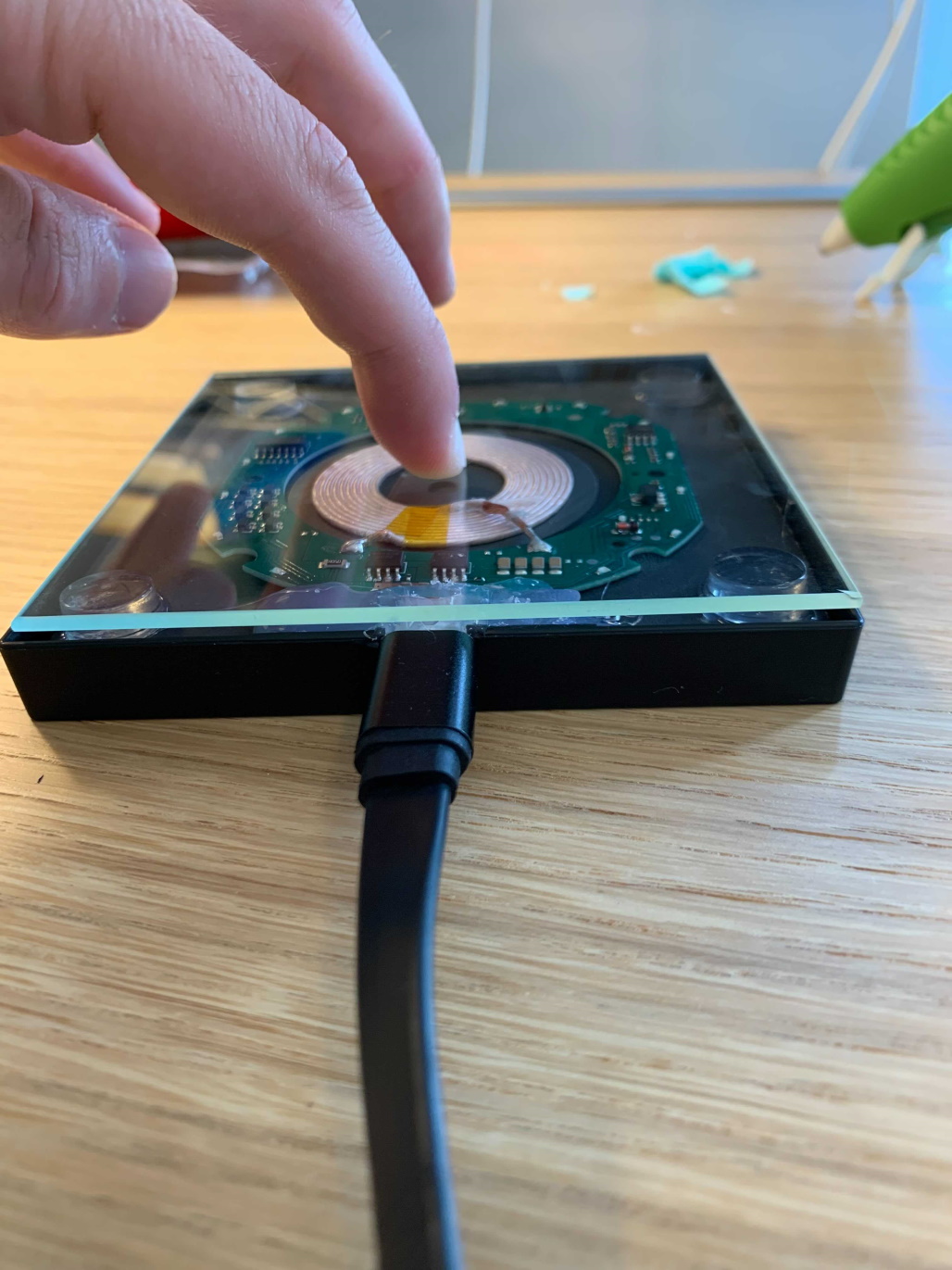
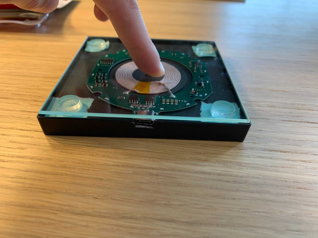
- Test the charger BEFORE moving forward!
- Plug it in
- Put phone on charger
- Ensure charger is working through glass and all functions as expected
- Secure the glass to the 1/2” bumpers
- Lift the glass and keep it nearby
- You’ll need to quickly line this up with the 4 corners of the frame and secure the glass before the hot glue cools
- Make sure you have enough hot glue in your gun to do ALL 4 at once!
- Quickly and precisely apply 4 small dabs of hot glue to the tops of the placed bumpers
- Line-up the 4 corners of the glass top with the 4 corners of the frame
- Place the glass onto the 4 bumpers into the hot glue
- Hold frame together briefly
- Let glue cool
- Lift the glass and keep it nearby
Apply pressure while the glue cools Glass top glued on the wireless charger

- (optional) Add 4 of the 1/2” bumper protectors to the bottom of the charger to act as non-slip feet
- I decided to keep mine flat on my desk instead of raising it with the non-slip feet
- 🎉 Tada! Your DIY Wireless charger is done and fully functioning!
Checkout the Final Result of Our DIY Wireless Charger Project
DIY Wireless Charger Illuminated DIY Wireless Charger Our DIY Wireless Charger!
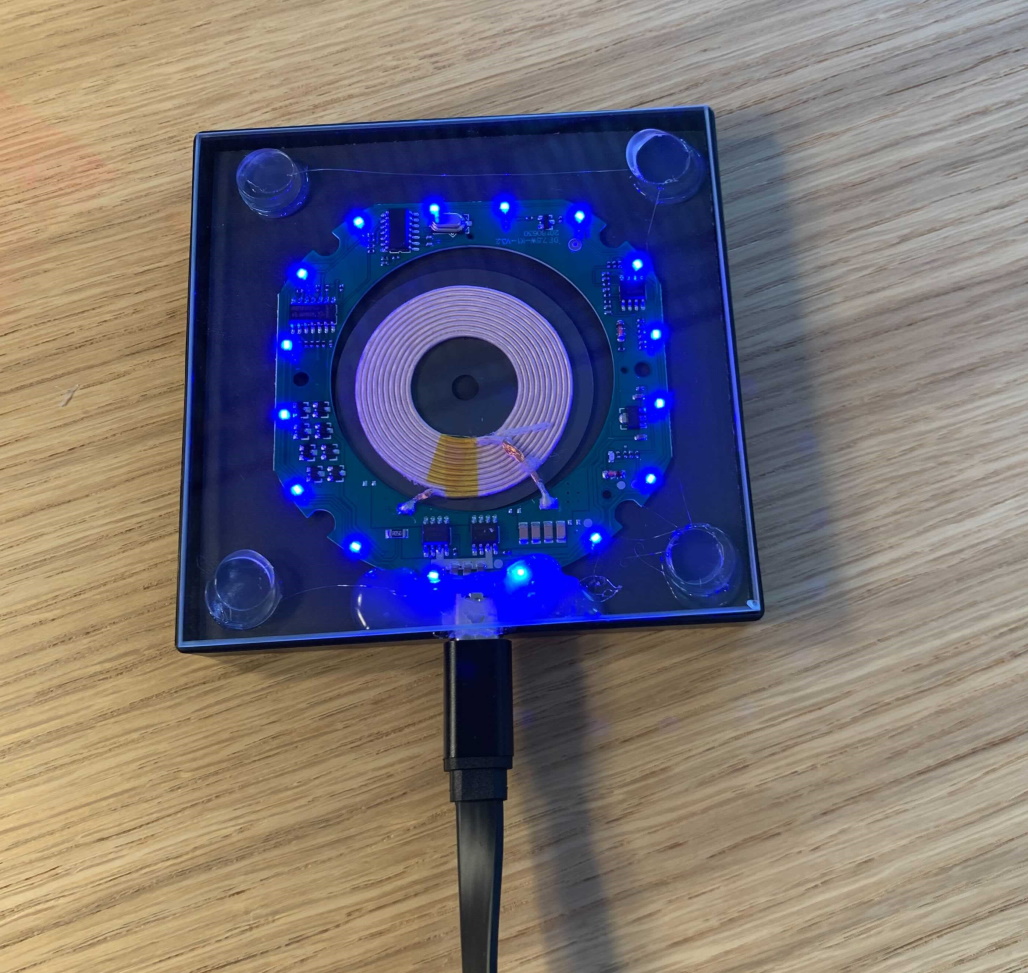
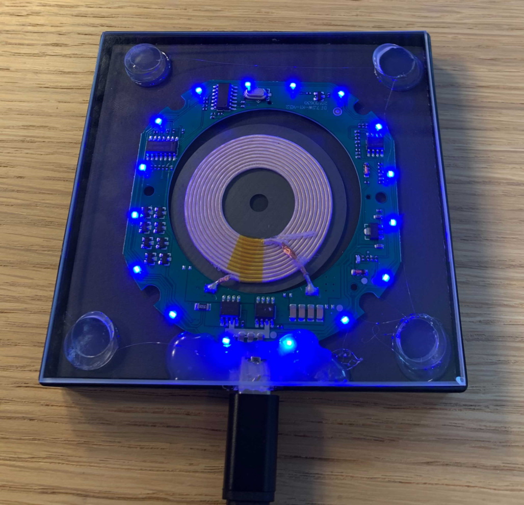
In less than an hour, we’ve been able to (pretty) effortlessly make a slick, usable 7.5W/10W wireless charger that is compatible with any Qi-enabled device. The wireless charger lights up with a vibey blue light when it is plugged in and charging a device. Let us know how your project turned out!
💬 Drop a comment if you have any questions about the DIY wireless charger! 💬